
Week 14
- Category:Interface and Application Programming
- Sessions Date: 26th Jan, 2022
- Assignment:
- Individual Assignment
Programming Using Processing Software
Week Assignment
ProcessingFor this assignment, we can utilize the Processing Code to create the application which will act as an interface with the MCU. Processing is a versatile software sketchbook as well as a programming language for writing code in the context of the visual arts. Processing has elevated software literacy in the visual arts and visual literacy in technology since 2001. Processing is used for learning and prototyping by several thousands of young people, artists, designers, experts, and hobbyists.

Downloading the Software
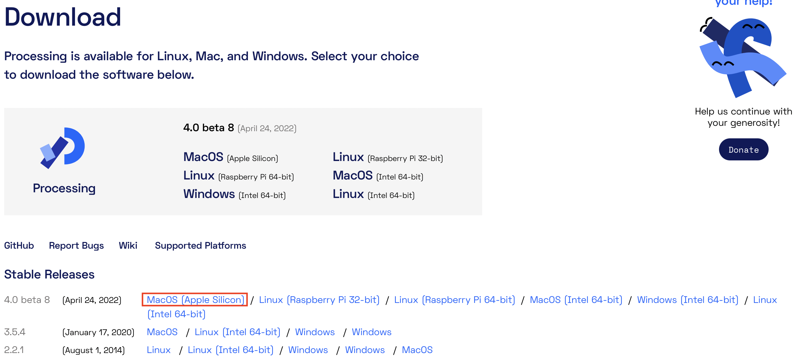
In order to use the “Processing” application first you need to download the software through the following link. Download Processing Software. For this particular assignment, I used a Mac laptop. Hence downloaded the 4.0 beta 8 version MacOS(Apple Silicon).
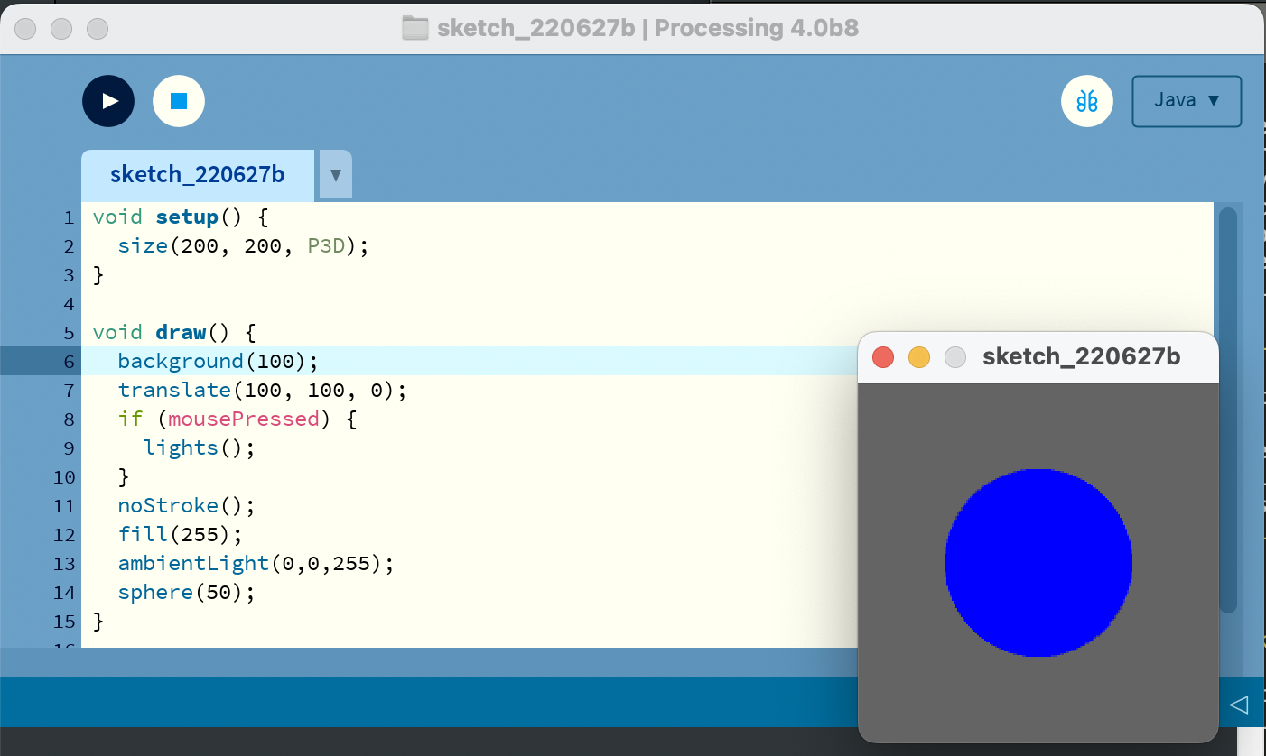
Once the software has been downloaded, install it and then play around with the new software. There are lots of code examples in the website of processing. I tried to copy a bunch of codes and then create a circle. Using the void setup() we can set the window of the application that we are going to make. It can be seen that inside the void parameter, there are three values. The three values in sequence represent the X-Axis, the second represents the Y-axis and the last one represents the height of the window.
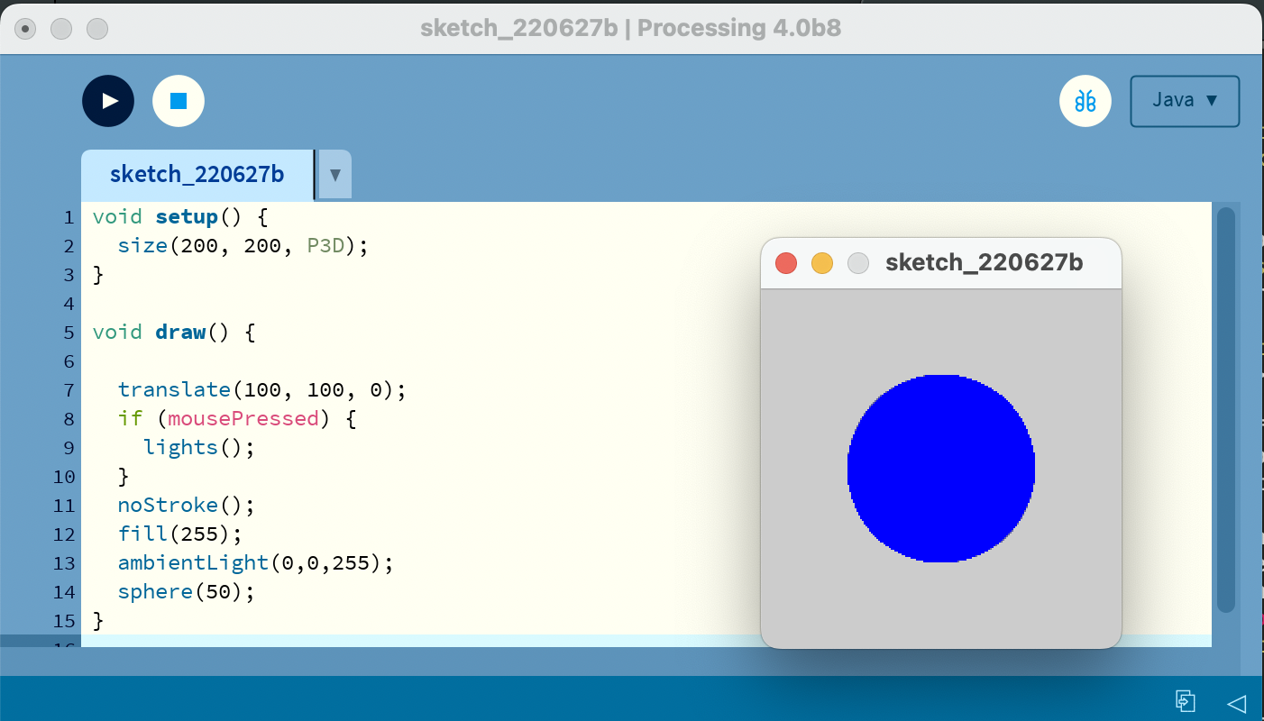
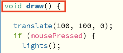
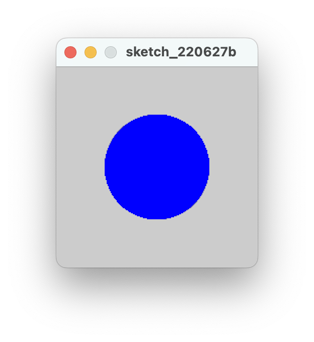
Void draw() is similar to that of void loop() when it comes to the adruino code. The commands are given inside the void draw() in the processing software. In the code below, I wrote a code that displays a blue circle. When the circle is clicked with the help of a mouse, the color of the circle changes into an ambient one.
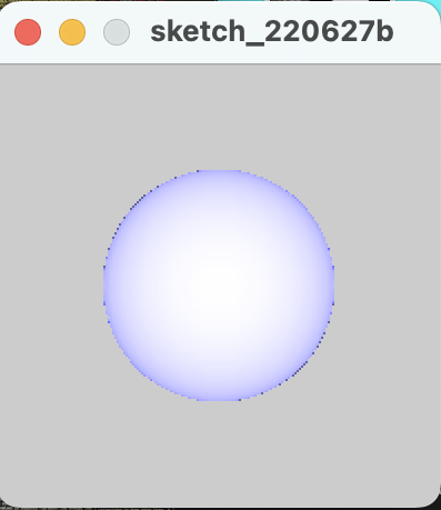
The video shows how the light turns on tne off when clicked.
Next I tried playing with the codes and then make it in such a way that the background color is different. I tried changing the color by changing the values of the background parameter.
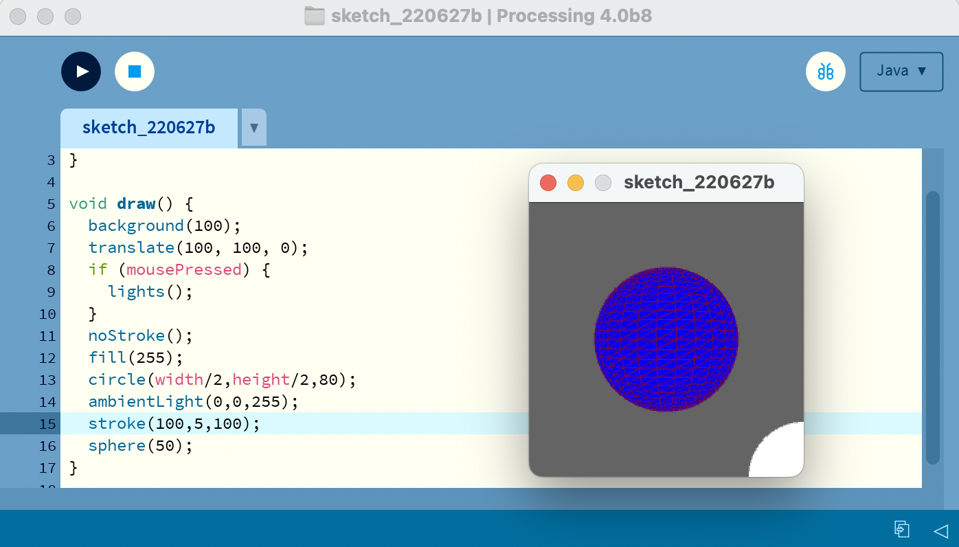
Next task that I completed was to make the fill of the circle that was created. The line of code circle(width/2,height/2,0) will help with the creation of circle of diameter 90. Width/2 and the height/2 are the positions of the circle in the x and the y axis respectively. Since the window was created with a dimension of 200 by 200 pixels the portions will be at 100 and 100 as well. (200/2=100). The stroke command is the border that exists around the circle. The thickness of the border is the shown by the strokeweight(90) and the color is given by the stroke.
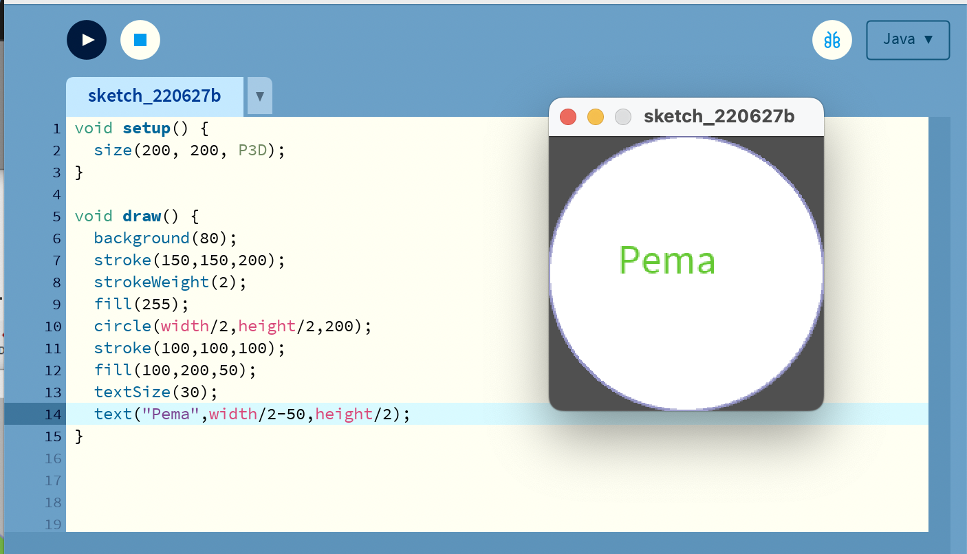
I tried playing more with the processing software and write letters inside the circle that was drawn. As shown below, the code text(“Pema”,width/2-50,height/2) was used to make the thing possible.
Processing Button Program
The main thing that has to be developed is an application using the processing and adruino IDE.The program that I want to develop is a program that sends a character (k) through the the utilization of serial communication. This is done by programming the program to the adruino program.
To use this we need the following code:
import.processing.serial.*;
Serial port;---> create Serial variable
port=new Serial(this, "COM_number", 9600); --->
Initialize Serial object
port.write("k:);
generate a Serial write event.
Arduino Programming
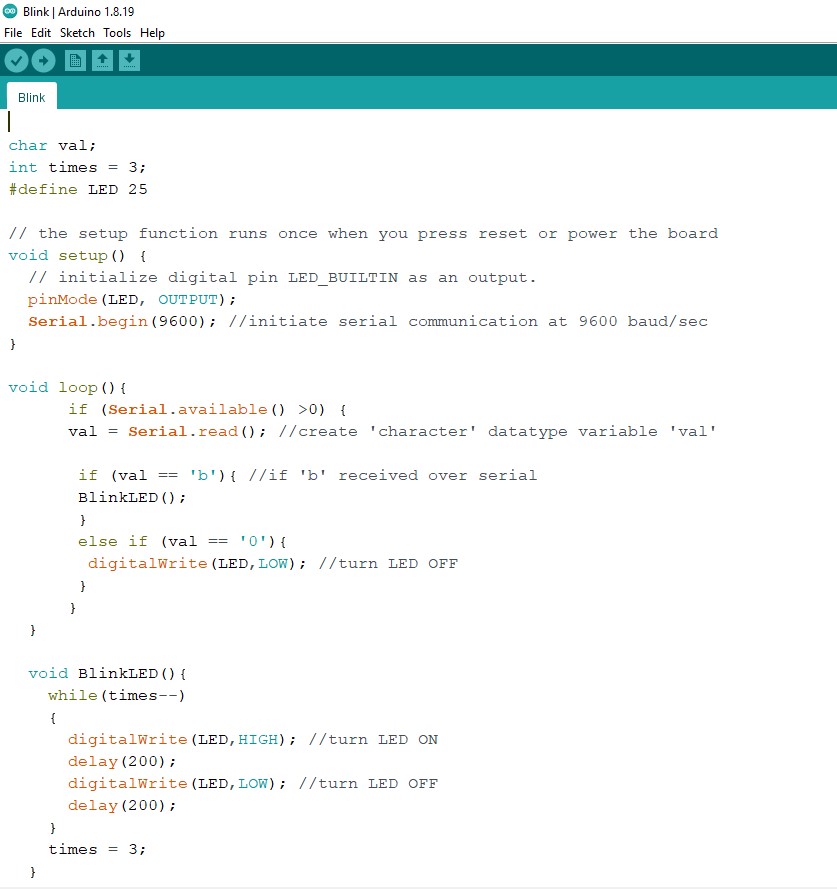
Adruino program that receives characters from the software called Processing through the Serial Communication connection and then it triggers an action through the MCU pins. The character that I have sent is the character b.
Preparing the Processing the Processing Software
Since you have already downloaded the processing software, only the set up part is left. Firstly you have to open it up and in the home window, navigate to Sketch-->Import Library-->Serial as shown beluw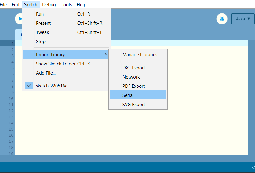
If you have imported the serial library well, the following line of code is displayed at the start of the code editor
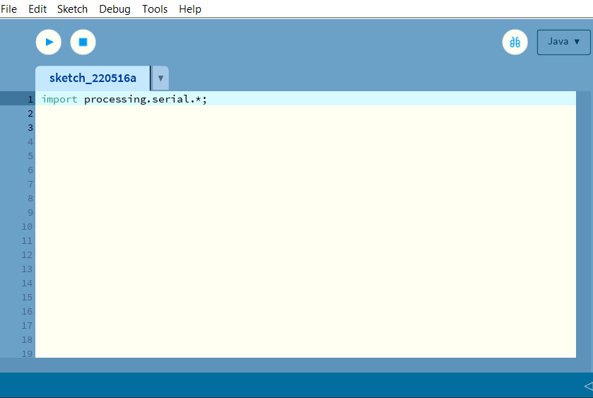
Now in the window, declare your global variables which can be utilised anywhere in the other parts of your sketch. In my case I have declared the the port number.

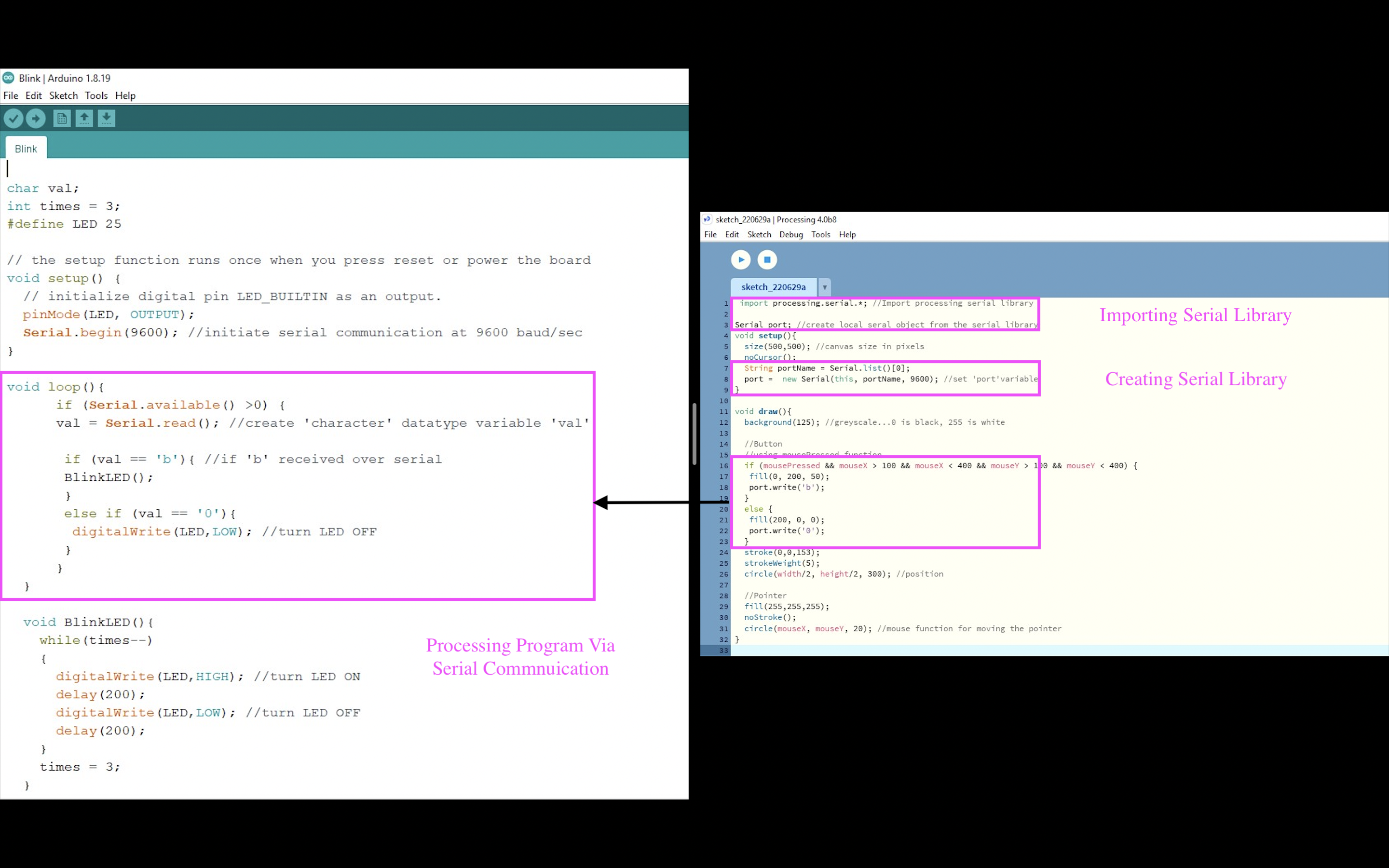
To listen to any serial communication, we must first obtain a serial object, which I refer to as My Serial Port (although we can call it whatever we like). This object will allow us to listen to a serial port on our computer for any incoming data. We also require a variable to get the real data. In my situation, I am sending a text, the letter "b," from Arduino, and in order to receive the string in Processing, we must first prepare Processing by using void setup() and void draw() instead of looping. In processing, I'll locate the serial port to which my Arduino is linked and configure my serial object to listen on that port.
Make sure the same baud rate is used in both Arduino and Processing so that it communicate at the same rate. Now hit the run button with the esp32 plugged in with the arduino code loaded, you will see the ‘b’ string in the Processing console
Processing Code
The two softwares use serial communications to communicate with each other as shown below:
Communication of Processing and my board
For this project, I will be using the Final Project board that was made during the output week. To carry out the serial communication between my laptop and the board, I connected the laptop by utilizing the FTDI connector. The FTDI connector for serial communication requires 4 pins. Though there are 6 pins in the board, 2 are not connected. The FTDI connector for communication uses the following 4 pins:
- VCC
- GND
- Rx
- Tx
To program the board, I connected the board using FDTI connecter and jumper wires. I also used a LED and breadboard since my board didnt hava a LED. One of the things that I want to do in my project is to light the LED. The connection for my assignment was done as shown below:
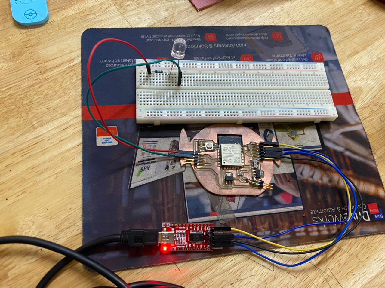
I want to glow the LED on my board. I have LED on Pin 25 in my ESP32 board. This means that in the Arduino IDE, it will be in Pin 3. I had already made all the changes in the first code itself. So there is no need to change the codes.
The processing programming stays the same. To put it simply, we are writing an application in Processing and transmitting it to my board using serial communication protocol using Arduino. The Arduino is used to comprehend and interpret the commands sent from Processing to the board. In this scenario, we are instructing the LED to light up when it receives the character 'b.' The mouse click is represented by the character 'b.'